
Parshall's measuring flumes
The specific Parshall flume is used to measure the instantaneous flow on the basis of the Q / h curve (dependence between the instantaneous flow and the level at the measuring point).
Properties
The Parshall flume is one of the flume with a long neck and is used mainly in localities with a balanced range of flows. For larger flow rates, it is advisable to use combined Parshall flumes.
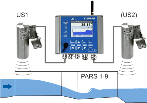
The advantage of the Parshall measuring flume is the fact that the overflow depth (level height) is measured in a tapering profile, where the velocity increases and the jets are more stable. Any sedimenting substances are deposited on the bottom of the riverbed before the measuring flume, and therefore this method of measurement is not usually sensitive to sedimentation, and at increased flows, undissolved substances are washed away behind the Parshall flume.
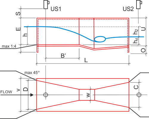
Dimensional table P1-P9:
| P1 | P2 | P3 | P4 | P5 | P6 | P7 | P8 | P9 |
Qmin [l/s] | 0,26 | 0,52 | 0,78 | 1,52 | 2,25 | 2,91 | 4,40 | 5,80 | 8,70 |
Qmax [l/s] | 6,22 | 15,1 | 54,6 | 168 | 368 | 598 | 898 | 1211 | 1841 |
hd / h [-] | 0,5 | 0,6 | 0,7 | ||||||
W [mm] | 24,4 | 50,8 | 76,2 | 152,4 | 228,6 | 304,8 | 457 | 610 | 914 |
B‘ [mm] | 300 | 340 | 390 | 530 | 725 | 1200 | 1300 | 1350 | 1500 |
C [mm] | 92,9 | 135 | 178 | 394 | 381 | 610 | 762 | 9144 | 1219 |
D [mm] | 168 | 214 | 259 | 397 | 575 | 845 | 1026 | 1207 | 1572 |
E [mm] | 230 | 264 | 467 | 620 | 800 | 925 | 925 | 925 | 925 |
L [mm] | 635 | 775 | 915 | 1524 | 1626 | 2867 | 2943 | 3019 | 3169 |
U [mm] | 248 | 286 | 492 | 696 | 876 | 1001 | 1001 | 1001 | 1001 |
V [mm] | 307 | 354 | 399 | 540 | 800 | 1000 | 1200 | 1400 | 1800 |
O [mm] | 46 | 64 | 82 | 191 | 191 | 176 | 176 | 176 | 176 |
S [mm] | 180 | 180 | 180 | 200 | 200 | 200 | 220 | 250 | 250 |
m [kg] | 9 | 10,6 | 19,1 | 49 | 81 | 146 | 183 | 231 | 252 |
Holder US | DUP1 | DUP2 | DUP3 | DUP4 | DUP5 | DUP6 | DUP7 | DUP8 | DUP9 |
Legend to the picture and to the table:
US1 Ultrasonic level sensor entering the ACH: Level channel
US2 Ultrasonic level sensor entering the ACH: Correction channel
Qmin minimum measurable flow [l/s]
Qmax maximum measurable flow [l/s]
h water depth at a distance B ‘in front of the neck [mm]
hd water depth behind the gutter (to the level of the bottom of the front part of the gutter) [mm]
hd / h maximum groundwater flooding ratio [-]
Consumption equations
The consumption equation of the Parshall flume has the form:
Q=A1*hA2 [m3/s; m]
The equation expresses the functional dependence between the instantaneous flow and the level at the specific point of the Parshall flume.
The preset coefficients A1 and A2 are intended for an ultrasonic level sensor located in the center of the trough in the direction of flow at a distance B ‘from the beginning of the flume neck. At this point, the level drop is still minimal and the reflected ultrasonic signal thus returns correctly to the sensor.
In FIEDLER AMS flowmeters, the coefficients A1 and A2 are already predefined, and when installing the flowmeter, all you have to do is select the correct size of the installed Parshall flume.
Backflow correction
Some installations do not allow to ensure a smooth drain from the Parshall measuring chute in all conditions so that insufficient drain does not affect the measurement. An example is the backflow of the level behind the gutter during a flood or when the drainage channel is clogged with dirt, etc., where non-compliance with this phenomenon would lead to the measurement of an unrealistically high flow rate.
Flow meters H3, H7, Q2 and M4016 allow to set a separate measuring channel for measuring the level behind the Parshall flume (ultrasonic sensor US2 from the above picture) and with its help to eliminate the measurement error according to ČSN ISO 9826.
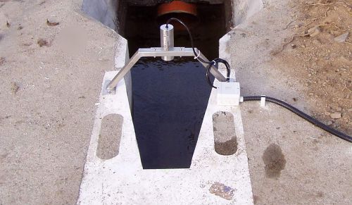
DUPx - ultrasonic level sensor holders
For easy and fast installation of the ultrasonic sensor, it is possible to order together with the sensor its holder DUP1 to DUP9 adapted to the dimensions of the Parshall trough and technical requirements of the ultrasonic sensor (measuring range of the sensor, dead band size, radiation angle).

