AIM600, AIM615 converters 4-20 mA/RS485

Characteristic properties
- 6 analog 4 (0) -20 mA inputs galvanically separated from the supply voltage and the RS485 serial line
- Measuring channels with a range of 0-100% of the measured value for each of the inputs
- Accurate 24 bit converters, conversion error <0.05%
- Error status detection above 20.75 mA and below 3.75 mA (for 4-20 mA ranges)
- FINET or MODBUS RTU protocol, adjustable address in the range of 60 to 75
- Low current consumption also adapted for battery-powered applications
- Overvoltage protection of inputs and outputs
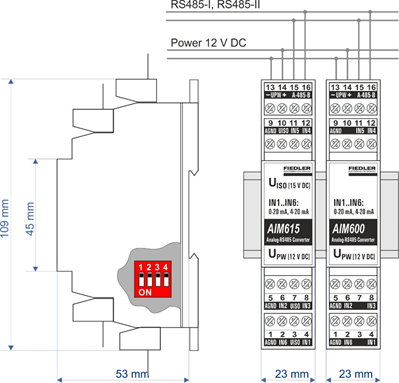
- Mechanical adaptation for installation on a 35 mm DIN rail
- Removable clamps for easy installation and service, module width only 23 mm
Examples of use
- Extension of the number of analog inputs of measuring stations and telemetry stations
- Connection of an analog signal to an optical line or radio network
- Addition of simple PLC and control units with the required number of analog inputs
Basic description
The AIM600 and AIM615 measuring modules are used to convert up to 6 current signals 0-20 mA or 4-20 mA to the RS485 data output under the FINET or Modbus RTU protocol.
The AIM615 module contains a galvanically isolated UISO supply voltage source of 15 V DC, intended for powering the connected measuring sensors and transducers. The AIM600 module allows the connection of only active current signals supplied from another voltage source.
Both converters are characterized by high measurement accuracy given by the used 24-bit converter, low own current consumption, supply voltage adapted for power supply from 12 V battery, galvanic separation of inputs from supply voltage and RS485 communication line and high reliability of operation without mechanical setting elements.
Measuring input IN1 to IN6
All 6 measuring inputs IN1 to IN6 are factory set to measure current in the range of 4-20 mA. Under the Modbus RTU protocol, the measuring range of the inputs can be reset to 0-20 mA. The actual measuring range of the transmitter allows to process current signals in the range of 0 to 22 mA.
Measuring channels K1 to K6
Each of the inputs IN1 to IN6 is assigned 1 measuring channel K1 to K6. The AIM6xx modules thus contain 6 measuring channels accessible via the RS485 bus under the FINET or Modbus RTU protocols. The value of each channel takes values in the range 0 to 100% according to the set measuring range 0-20 mA (0 mA = 0%) or 4-20 mA (4 mA = 0%).
Error messages:
An increase in the measured current above 20.75 mA is signaled on the respective channel by error code E25. For the measuring range of 4-20 mA, a current drop below 3.75 mA is also signaled by this error code.
An input current of less than 3 mA (or disconnection of the input from the signal source) is signaled by error code E13.
UISO output voltage
The AIM615 module contains a galvanically isolated voltage source UISO = 15 V DC, intended for powering the connected measuring sensors. The total current consumption from this source must not exceed 120 mA to avoid measurement error.
The AIM600 module does not contain a UISO power supply and therefore only allows the connection of active current signals supplied from another external power supply.
Connection of the module to the superior control unit via RS485
Both AIM600 and AIM615 modules communicate with the H3, H7, Q2 or E2 control unit in the basic settings via the RS485 bus under the FINET protocol at a speed of 19200 Bd, 1 stop bit, no parity.
By default, each module has the basic communication address ADR = 60. The user can use the 4-pole switch on the module board to set 16 combinations in the range 0 to 15, which are added to the basic communication address 60. The combination is set binary, ie as the sum of the weights of the individual closed bits 1, 2, 4 and 8. Address switch it is accessible after opening the lower cover of the box.
The individual setting of the communication address is used, for example, when connecting several AIM6XX modules to one RS485 bus (each module in the network must have a unique communication address).
When parameterizing and setting the recording channels of the control unit, it is necessary to enter the number of the measuring channel K1 to K6 in addition to the communication address of the module. The number of AIM6XX modules that can be connected to one control unit is thus practically limited only by the number of recording channels of this unit.
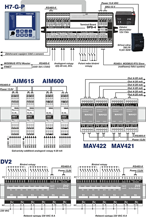
Example of connecting I/O modules to the H7 unit
Technical parameters
AIM600 | AIM615 | |
Inputs | IN1 až IN6, measuring range 4(0)-20 mA | |
Measurement error | <± 0.05% of range, accurate 24 bit converter | |
Measurement time | <0.3 s / 1 measuring channell | |
Input resistance | 50 Ω | |
Output RS485 | Channels K1 to K6 on RS485 under FINET protocol (MODBUS RTU) | |
Com. address | 60 + on-board switch (0 to 15) | |
Measuring range | 0 to 100% [-] from the range 0 (4) -20 mA, float format (10000 = 100%) | |
Power voltage | 6 to 26 V DC / I < 15 mA | 11 to 13 V DC / I < 180 mA |
UISO output | - | 15 VDC /galv. separation 1000 V |
Temperature range | -25 °C to +60 °C | |
Dimensions / IP | 109 x 23 x 57 mm / IP 20 (width 1 module / DIN rail) | |


Documentation
Download
Application
no related solutions